Fiber Route
The command manually routes fiber on the map. Before routing fiber, make sure you have attached/queried the necessary Strand data for the area if using Link to Strand drafting mode.
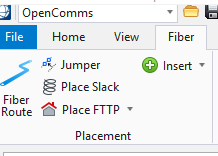
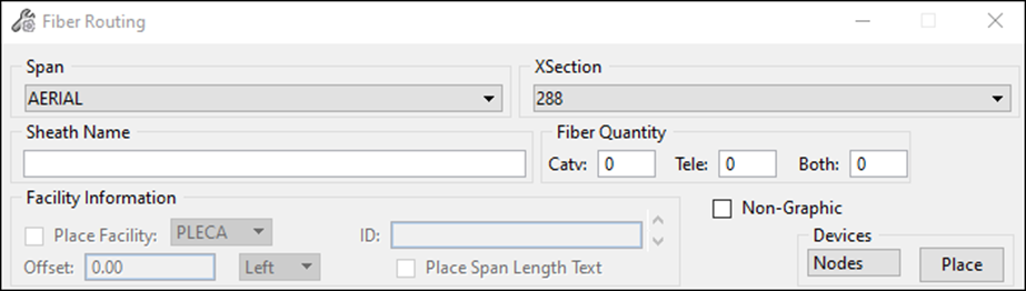
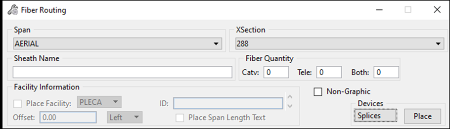
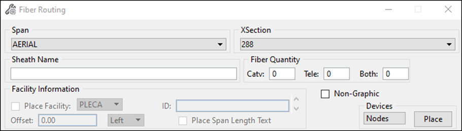
- Click the Fiber Route icon and the following dialog displays:
- It is now possible to start routing by either placing a new piece of equipment, or by selecting existing equipment from which a new span is placed.
Placing Equipment
- Select an equipment device type from the devices pull-down menu.
- If the Link to Strand setting option is activated, you are asked to select a strand device on the map in which to link the equipment.
- A dialog box opens in order to choose the model that will be used. If more than one model has been entered for an equipment type, select the pull-down button and drag down to the model that is to be used.
- Click OK to confirm the selection.
- Place the equipment on the map or press Reset to change the angle of the device. If Reset is selected, next select two points on the map using the Data button to set the angle.
- After placing the device, you are prompted to enter an ID or name.
- Key in an ID or name and press Enter.
- Place the equipment annotation on the map.
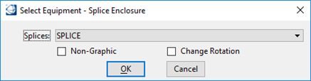
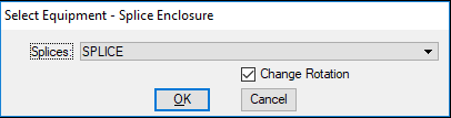
- Place a span. After Placing
the Span Select the Splice Enclosure from the Select Equipment dialog, check
the 'Change Rotation' button to set the angle (if desired). Enter the Name and
place the splice to terminate the Span.
Note: If the proper drafting of the new fiber sheath feature requires a vertex or multiple vertices, use the SS keyin command (suspend) to start drafting with vertices. Once the sheath is drafted properly, use the SS keyin command again to end the placement of vertices and finalize the drafting of that sheath segment. While routing, press Reset (right click by default) to center the active view.

Place a Span on Existing Strand (Aerial or Direct Bury Underground)
- Activate the Link to Strand setting under Fiber/Copper/ISP-Setup > Settings.
- From the Fiber Routing dialog box, select a Span type from the Span pull-down menu. Choose a cross section to apply to the selected span and specify the fiber quantity to use for each category.
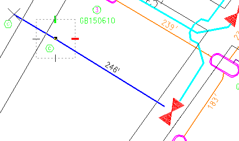
- Select a distance on the map
to start placing fiber span.
Note: If the proper drafting of the new fiber sheath feature requires a vertex or multiple vertices, use the SS keyin command (suspend) to start drafting with vertices. Once the sheath is drafted properly, use the SS keyin command again to end the placement of vertices and finalize the drafting of that sheath segment. While routing, press Reset (right click by default) to center the active view.

Place a Span and Pole or Pedestal Facilities Simultaneously
- Activate the Calculate Distances setting under Fiber/Copper/ISP-Setup > Settings (if not already selected).
- Activate the Place Facility check box to place a pole or pedestal while routing fiber.
- From the Fiber Routing dialog box, select facility type, facility ID, the span Offset and the side from where the facility will be placed.
- Select a Span type from the Span pull-down menu. Choose a cross section to apply to the selected span and specify the fiber quantity to use for each category.
- Activate the Place Span Length Text check box to automatically place span length text on the map.
- Select the device from which to start routing fiber span.
- While routing, press Reset (right click by default) to center the active view. An additional key in option U will Undo the last device that was placed.
- When ready to place another device, such as a splice, select it from the Equipment Menu, enter an ID or name and select the next distance text.
- Selecting a node from the Equipment Menu terminates the fiber run. If a node has been selected, a prompt displays to select a device (another device) from the Equipment Menu or link to existing equipment.
Place Span Inside Conduit (Graphically Display the Sheath Feature)
- Activate the Link to Strand setting under Fiber/Copper/ISP-Setup > Settings (if not already selected).
- Select the fiber feature from which you plan to start routing a fiber span or place a new feature by selecting an equipment type from the Equipment menu.
- If placing new equipment, the equipment dialog opens.
- Once a device has been chosen, choose OK in the Select Equipment dialog and select the duct enclosure feature that will house this new fiber feature.
- If routing from an existing fiber feature or after a new fiber feature has been placed, select the fiber feature and then choose the duct path that holds the conduit you wish to populate.
- The Conduit Selection dialog box appears.
- In the Conduit Selection dialog box, select the conduit you wish to populate and choose OK.
- The new fiber sheath feature
will be emanating from the fiber device feature and can be drafted to the next
duct enclosure location.
Note: If the proper drafting of the new fiber sheath feature requires a vertex or multiple vertices, use the SS keyin command (suspend) to start drafting with vertices. Once the sheath is drafted properly, use the SS keyin command again to end the placement of vertices and finalize the drafting of that sheath segment. While routing, press Reset (right click by default) to center the active view.
- Continue this same process for the entire duct network being populated.

Place Span Inside Conduit (Non-Graphical Sheath Placement Option)
- Activate the Link to Strand setting under Fiber/Copper/ISP-Setup > Settings.
- From the Fiber Routing dialog box, activate the Non-Graphic check box.
- Select the fiber feature from which you plan to start routing a fiber span or place a new feature by selecting an equipment type from the Devices dropdown.
- If placing new equipment, the equipment dialog opens.
- Once a device has been chosen, activate the Non Graphic check box and choose OK.
- Select the duct facility on which to attach the newly created feature and place the equipment and its annotation on the map.
- Select the duct on the map where the span is to be placed.
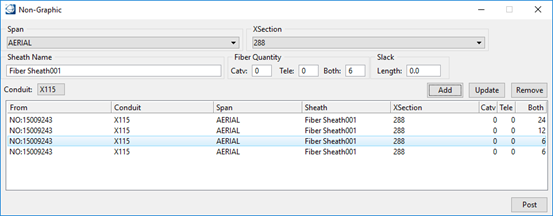
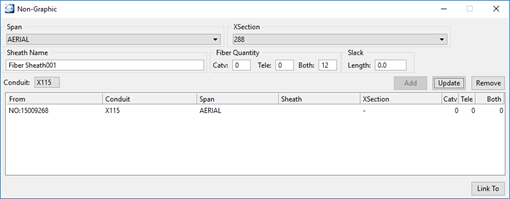
- The Non-Graphic dialog box opens.
- From the Conduit pull-down menu, select the conduit where the new sheath will reside.
- Click Add to add the span in the list, or Remove to remove it from the list.
- Click Post to complete and accept the span placement.
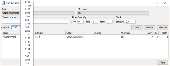
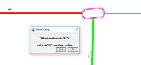
- The Select Routing dialog box opens.
- Select the appropriate conduit section to continue routing.
- From the Conduit pull-down menu, select the conduit where to place the span.
- Click Post to continue.
Note: If routing to an enclosure where a fiber feature is to be placed, a window opens asking if the span should be connected to that location.